
How to Test an AC Capacitor: Step-by-Step Guide
- Bryn Fortmuller
- Jul 28
- 9 min read
A humming outdoor unit with a fan that won't spin is one of the most common summer service calls, and a failed run capacitor is usually the reason. The good news: a replacement part costs $15, $30, and you can confirm the diagnosis yourself before incurring a service visit cost. This guide walks you through every step safely, including the tolerance benchmark that most online guides skip entirely.
Step 1: Turn Off Power and Secure the Unit
Your goal here is complete electrical isolation. The capacitor holds a charge even after the system shuts off, so cutting power at just the thermostat is not enough.
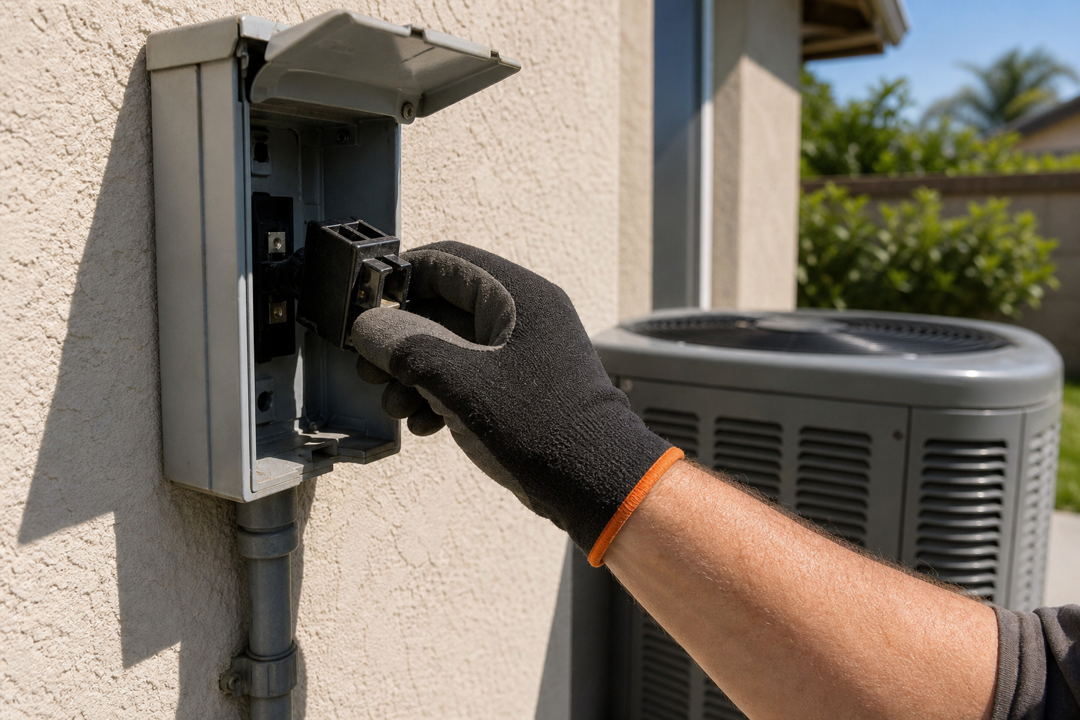
First, flip the AC breaker in your main electrical panel to the off position. Then walk to the outdoor condenser and pull the disconnect block from the small weatherproof box mounted on the wall nearby. You need both steps. The breaker kills the main feed. The disconnect block removes any chance of the circuit re-energizing through a delay relay, which some units have.
Before you touch anything inside the unit, put on insulated gloves and safety glasses, as most HVAC testing sources recommend them as required PPE.
Now remove the access panel on the condenser, usually held by two or three screws. Look for a silver or black metal cylinder mounted against the side wall inside the service panel. That's the capacitor. Capacitors typically have terminal markings; many have three terminals labeled HERM, FAN, and COMMON, while others have two terminals.
Check the label on the capacitor now. Note the MFD (microfarad) rating and the voltage rating, either 370V or 440V. You'll need these numbers in Step 3. If the capacitor is visibly bulging or leaking oil, skip ahead to Step 5 and order a replacement. There's nothing to test on a physically failed part.
For a sense of what this repair costs if you decide to hand it off, our breakdown of heat pump repair costs covers capacitor and contactor replacement in detail, including typical labor ranges in the Placer County area.
Key Takeaway:Two separate power cuts are required: the main breaker AND the outdoor disconnect block. One alone is not enough.
Step 2: Discharge the Capacitor Safely
This is the step most DIYers skip, and it's the one that sends people to the emergency room. A capacitor can deliver a serious jolt even after the power is off. You must discharge the stored charge before touching the terminals.
Grab a well-insulated screwdriver. Hold it firmly by the insulated handle only. Touch the metal shaft across two terminals at a time to bridge them and safely dissipate the charge. For a typical run capacitor with multiple terminals, bridge each pair of terminals (e.g., HERM to FAN, HERM to COMMON, and FAN to COMMON). Work through each pair once. You may hear a small pop or see a brief spark. That's normal.
Some technicians use a resistor in series with the screwdriver to slow the discharge and reduce the spark. It's a cleaner method if you have one available, but the insulated screwdriver alone works fine for a standard run capacitor.
Once you've bridged all terminal pairs, the capacitor is safe to handle. Now use needle-nose pliers to pull the wire connectors off each terminal, and use a marker or tape to label each wire before you remove it. Taking a photo with your phone works just as well. You want to know exactly where each wire goes when you reassemble.
The single biggest testing mistake cited across the sources we reviewed is handling the capacitor without discharging it first. It can produce a shock hazard and also corrupt your meter reading if residual charge interferes with the measurement. Don't skip this step.
Step 3: Measure Capacitance with a Digital Multimeter
With the capacitor fully discharged and disconnected from the circuit, you're ready to measure. This is the most reliable test method available to a homeowner.
Set your digital multimeter to the capacitance function, marked with the µF or Cx symbol. Not every multimeter has this mode. If yours only reads voltage and resistance, the capacitance test isn't possible with that tool. According to Fluke's official documentation on measuring capacitance , you should always confirm power is completely off and wear appropriate PPE before taking a measurement on any capacitor.
Touch the red probe to the positive terminal and the black probe to the negative terminal. When testing a capacitor with multiple terminals, test the compressor side (HERM to COMMON) first, then the fan side (FAN to COMMON). Wait a few seconds for the reading to stabilize.
Now compare your reading to the MFD value on the capacitor's label. Here's the benchmark most guides leave out: a healthy capacitor reads within ±5, 6% of its rated value. Only about 24% of the guides we examined actually provide this tolerance, which leaves most DIYers guessing whether a reading is good or not.
Here's how the math works in practice. Say your capacitor is rated at 35 µF. Multiply 35 by 0.06 to get 2.1. Your acceptable range is 32.9, 37.1 µF. A reading of 31 µF means the capacitor is weak. A reading of 0 or "OL" (open loop) means the internal circuit is broken and the part is dead regardless of how it looks.
Pro Tip:If your multimeter shows "OL" on the capacitance setting, the capacitor has an open internal circuit. Order a replacement and match both the MFD rating and the voltage rating (370V or 440V) exactly from the label.
By this point you should have a µF reading for each side of the capacitor and know whether it falls within the ±6% tolerance band. If it does, the capacitor is electrically healthy. If it doesn't, you've confirmed the failure.
Step 4: Under-Load Test & Compare Methods
The bench test in Step 3 covers most situations. But if your readings land right at the edge of the tolerance band, or if the system still struggles after you've reinstalled a capacitor that tested fine, an under-load test gives you a second opinion with the system actually running.
This test requires a multimeter set to AC voltage and a suitable current measuring device. With the system running, place the current measuring device around the start winding lead that runs between the capacitor and the motor. Then measure the voltage directly across the capacitor terminals with your multimeter probes. Use the appropriate calculation to determine the effective capacitance.
Effective capacitance can be calculated from the measured current and voltage.
Compare that result to the nameplate rating using the same ±5, 6% rule from Step 3. If the calculated value falls outside that window, the capacitor is struggling under real operating conditions even if it looked acceptable on the bench.
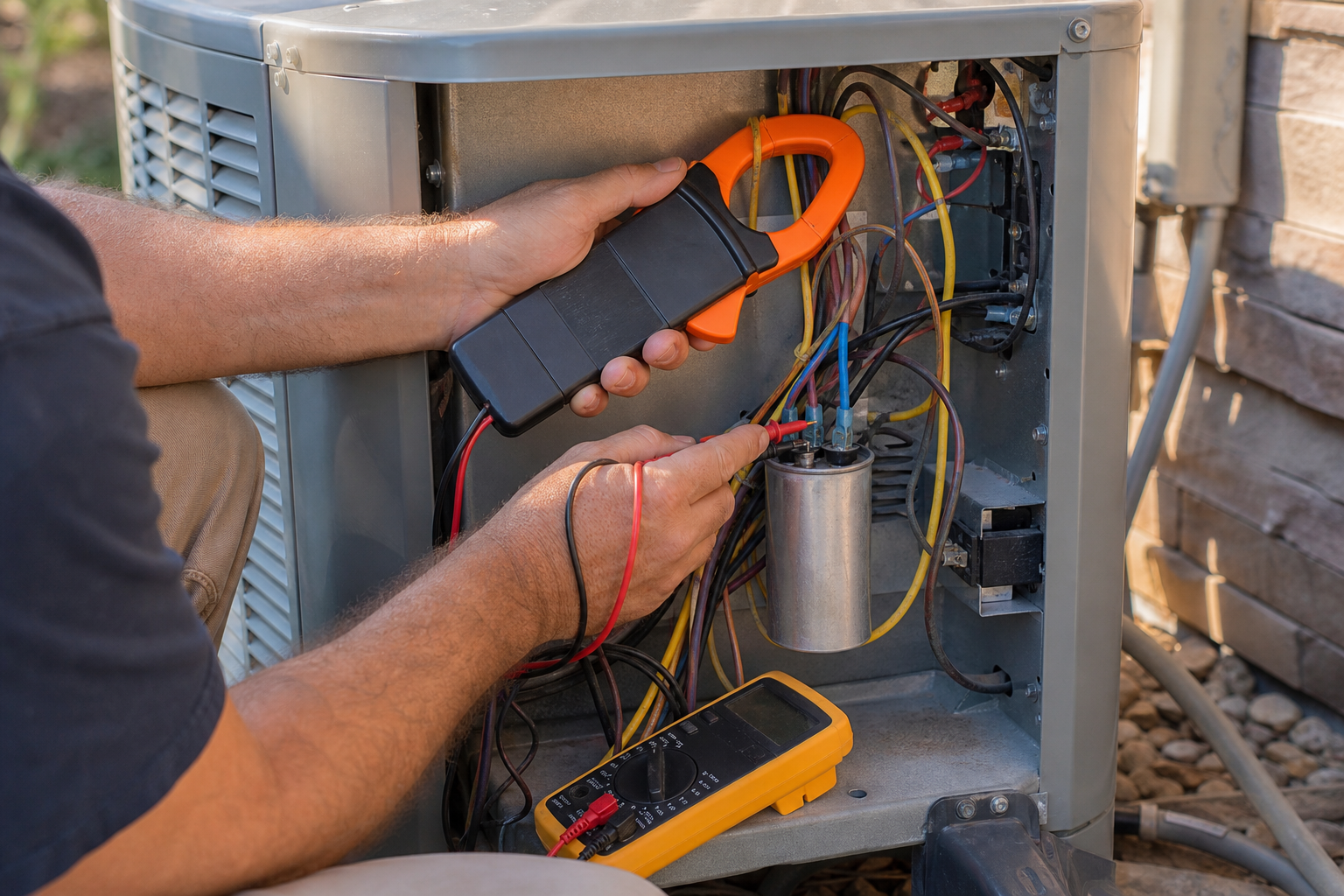
One honest caveat about the under-load method: it can make a good capacitor look bad if your technique is off. Measuring the wrong lead or placing the current measuring device incorrectly shifts the numbers enough to flag a healthy part. The bench test in Step 3 is more reliable for most homeowners. Use the under-load test as a confirmation tool, not a first step.
Test Method | Tools Required | System State | Accuracy | Best For |
Capacitance (µF) Test | Digital multimeter with µF function | Power OFF, capacitor disconnected | High | First-pass diagnosis for most homeowners |
Under-Load Test | Multimeter | System running (live voltage) | Moderate (technique-sensitive) | Confirming borderline bench results |
Visual Inspection | None (flashlight optional) | Power OFF | Low (misses internal failures) | Quick pre-test screening only |
Resistance Mode Test | Standard multimeter (no µF mode) | Power OFF, capacitor disconnected | Low (can mislead experienced techs) | Last resort when no µF-capable meter is available |
If you're not comfortable working with live voltage for the under-load test, that's a completely reasonable line to draw. The team at Home Worx Heating and Cooling carries the right test equipment and can run both methods safely during a service visit for homeowners in Placer and Nevada County.
Step 5: Visual Inspection for Physical Damage
Visual inspection alone won't tell you if a capacitor is weak. A capacitor can fail electrically while looking completely normal on the outside. But a visual check takes 30 seconds and can save you from handling a damaged component that shouldn't be touched at all.
With power off and the capacitor discharged, look at the top and sides carefully. Two signs tell you the part is done without any meter test:
A bulging or domed top (the metal should be flat)
Any oily residue or brown staining around the terminals or seams
Either of those means the capacitor has vented or is on the verge of it. Don't attempt to discharge or test it further. Order a replacement and match both the MFD and voltage ratings from the label exactly.
Also check for corrosion on the terminals themselves. Light surface oxidation is common in outdoor units, especially here in the Sierra foothills where temperature swings between hot dry summers and cold winters stress components over time. Heavy corrosion at the terminal connections can cause resistance in the circuit that mimics a weak capacitor reading, so clean the terminals with a brush before testing if you see buildup.
One thing sources consistently flag: ignoring early signs like slight swelling or minor corrosion can allow a failing capacitor to cause compressor damage. The compressor strains harder when the capacitor is weak, and that heat and stress shortens its life. Catching a bad capacitor early is one of the most cost‑effective things you can do for your AC system.
If your system passes all five steps but still struggles on the hottest days, the problem may be a borderline capacitor that only fails under high ambient heat, or the motor itself. A non‑conductive stick to nudge the fan blades manually (with power off) can tell you if the motor bearings have seized. A good capacitor can't spin a locked motor. At that point you're looking at a motor replacement, which is a different conversation. Our guide on furnace maintenance checklist items covers how regular seasonal checks prevent exactly this kind of cascading failure across your whole HVAC system.
If anything in this process feels outside your comfort zone, the right call is to stop and get a professional in. Home Worx Heating and Cooling offers 24/7 emergency service across Placer and Nevada County, and a technician can run through all of these tests safely and accurately in a single visit.
FAQ
How do I know if my AC capacitor is bad without a multimeter?
The most reliable signs without a meter are a humming outdoor unit where the fan won't spin, the system struggling to start on hot days, or a tripped breaker shortly after startup. A visually bulging top or oily residue around the capacitor seams also confirms failure. That said, these symptoms overlap with other issues, so a multimeter with a µF function is the only way to confirm the capacitor specifically.
What reading should an AC capacitor give on a multimeter?
A healthy capacitor reads within ±5, 6% of the MFD value printed on its label. For a 35 µF capacitor, the acceptable range is roughly 32.9, 37.1 µF. A reading below that range means the capacitor is weak. A reading of zero or "OL" means the internal circuit is open and the part needs replacing.
Can I test a capacitor while it's still wired to the AC unit?
No. Testing a capacitor while it's still connected to the circuit is the single most common mistake in DIY capacitor testing. It produces falsely low readings because the circuit load interferes with the measurement. It also poses a shock risk if the capacitor isn't fully discharged. Always disconnect the wires before measuring capacitance.
Is it safe to test an AC capacitor myself?
Yes, if you follow the safety steps in order: cut power at both the breaker and the outdoor disconnect, discharge the capacitor by bridging all terminal pairs with an insulated screwdriver, and wear insulated gloves and safety glasses throughout. Skip any one of those steps and the risk increases significantly. If you're not comfortable around electrical components, call a licensed HVAC technician.
How much does it cost to replace an AC capacitor?
The part itself typically costs $15, $30 for a standard run capacitor. A professional service call to diagnose and replace one typically costs a few hundred dollars in most markets, including parts and labor. Matching both the MFD rating and the voltage rating (370V or 440V) exactly when buying a replacement is important. Using the wrong spec can damage the new part or other components in the system.
What tools do I need to test an AC capacitor?
You need a digital multimeter with a µF (capacitance) function, a well-insulated screwdriver for discharging, insulated gloves, safety glasses, and needle-nose pliers to pull wire connectors. A marker or tape to label wires before removal saves headaches on reassembly. For an under-load test, you also need a multimeter capable of measuring current.
For reliable AC capacitor testing or replacement in Placer and Nevada Counties, contact Home Worx Heating and Cooling.
Conclusion
Testing an AC capacitor comes down to five steps done in order: power off at both the breaker and the disconnect, discharge the capacitor before touching it, measure capacitance with a µF-capable multimeter and compare to the ±6% tolerance on the label, run an under-load test if the bench result is borderline, and do a quick visual check for swelling or leaks. If the readings are outside tolerance or the part shows physical damage, replace it. And if any step feels uncertain, the team at Home Worx Heating and Cooling serves Placer and Nevada County with 24/7 availability. Reach out through callhomeworx.com to schedule a diagnostic visit.